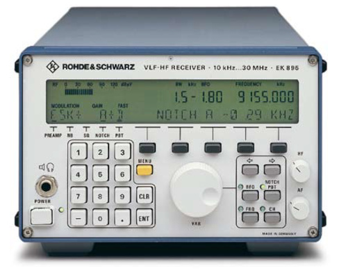
High performance triple-conversion VLF / HF radiomonitoring receiver. After digitization of the third IF in a 16-bit ADC the processor assumes all signal processing tasks including 13 fixed or quasi-continuously adjustable bandwidths, passband tuning, double notch filter. High dynamic range with +35 dBm IP3. Ideated in Germany.
Reference market : professional
EK895 specifications
| General |
| Frequency coverage | |
|---|---|
| 0.0100 ~ 30.0000 MHz | |
| Mode | |
| CW / FSK / LSB / USB / ISB / AM / FM | |
| Tuning step | |
| 1 Hz min |
| Receiver |
| Sensitivity | |
|---|---|
| CW | 0.4uV EMF (0.1~30 MHz, 10dB S/N, BW 300 Hz, pre OFF).
0.2uV EMF (0.2~30 MHz, 10dB S/N, BW 300 Hz, pre ON) |
| SSB | 1.0uV EMF (0.1~30 MHz, 10dB S/N, BW 2.7 kHz, pre OFF).
0.4uV EMF (0.2~30 MHz, 10dB S/N, BW 2.7 kHz, pre ON) |
| AM | 2.7uV EMF (0.1~30 MHz, 10dB S/N, BW 6 kHz, pre OFF).
1.0uV EMF (0.2~30 MHz, 10dB S/N, BW 6 kHz, pre ON) |
| Selectivity [2] | |
| CW | 150 Hz (-3dB)
300 Hz (-60dB) |
| SSB | 2.7 kHz (-3dB)
3.8 kHz (-60dB) |
| AM | 6.0 kHz (-3dB)
8.4 kHz (-60dB) |
| FM | 8.0 kHz (-3dB)
10.4 kHz (-60dB) |
| ADC (Analog to Digital Conversion) | |
| Resolution | 16 bit |
| IF output frequency | |
| 1.44 MHz | |
| IF output bandwidth | |
| 10 kHz (-3dB) | |
| Gain RF to IF | |
| 18dB | |
| Gain flatness | |
| ± 2dB | |
| RF preamplifier | |
| ~10dB | |
| IP2 (2nd order intercept point) | |
| +70 dBm typ (1.5~30 MHz) | |
| IP3 (3rd order intercept point) | |
| +35 dBm typ (1.5~30 MHz) | |
| RF maximum input level | |
| 100V EMF | |
| Image rejection | |
| >90 dB | |
| IF rejection | |
| >90 dB | |
| Spurious response | |
| -124 dBm typ | |
| BFO range | |
| ± 5 kHz (10 Hz steps) | |
| PBT (Passband Tuning) | |
| Yes | |
| Notch filter | |
| Yes | |
| NB (Noise Blanker) | |
| Yes | |
| AGC (Automatic Gain Control) | |
| Automatic, manual or remote.
Attack time <15 ms Decay time 0.025 / 0.15 / 0.5 / 1 / 3 s |
|
| Frequency stability | |
| ± 0.5ppm with temperature from -10°C to +45°C.
± 0.1ppm with OCXO unit [1] |
|
| Synthesizer settling time | |
| 5 ms | |
| IF (Intermediate Frequency) | |
| 1° | 41.44 MHz |
| 2° | 1.44 MHz |
| 3° | 25 kHz |
| IF roofing filter | |
| 10 kHz | |
| Audio response | |
| 0.3~3.4 kHz | |
| Features |
| Memory | |
|---|---|
| 1000 channels | |
| Display | |
| 1 Hz frequency resolution
24-segments signal meter bar |
|
| Antenna | |
| BNC 50Ω
VSWR <1.5:1 (<0.25 MHz, preamplifier ON) VSWR <3:1 (>5 MHz, preamplifier ON) |
|
| IF output | |
| BNC 50Ω | |
| Power supply | |
| 100~240 VAC | |
| Audio output | |
| Jack 6.35 mm headphone | |
| I/Q output | |
| Baseband signal | |
| Connections | |
| RS-232C
RS-485 BNC (1 / 5 /10 MHz reference input) IF output (1.44 MHz) IF output (0 to 40 kHz / 455 KHz) |
| Mechanical and environmental data |
| Operating temperature | |
|---|---|
| from -10°C to +45°C | |
| Dimensions | |
| 211 (W) x 132 (H) x 460 (D) mm | |
| Weight | |
| ~8kg |
- Optional oven-controlled frequency standard (OCXO).
- Bandwidths example, the following table shows all filters.

Updated | Complete | UK - NORTHERN IRELAND
378 pages | 300+ Airports and Airfields
Voice com. | ACC | FIC | VOLMET | ACARS | VDL | ILS | VOR | DME
The Rohde & Schwarz EK895 is a compact DSP-based receiver for radiomonitoring and professional radio detection. Straight forward, menu-guided selection and programming of the receiving settings ensure excellent processing and handling of the received signal content. With its excellent RF characteristics and clearcut, full remote-control capability, the EK895 is suitable for all civil, administrative and military shortwave applications. The built-in memory has capacity for non volatile storage of 1000 complete channel settings so that channel management and control by an external PC are not required but are nevertheless additionally possible. Due to his excellent characteristics regarding dynamic range, low synthesizer noise and gain control range, the receiver are ideal high-performance frontends for subsequent signal processing.
In the standard version, the Rohde & Schwarz EK895 is available with an operator front panel. This front panel also permits manual control and display of all functions while full remote-control capability is maintained. This version is particularly suitable for use as a master receiver in receiving systems or as a standalone unit. The operator interface allows for a combination of hardkey and softkey entries. Parameters that are frequently handled, i.e. receive frequency, channel, BFO frequency and passband tuning (PBT), can be entered directly. All current receiver settings are continuously displayed in large high contrast characters on a backlit LCD. An additional bargraph indicator allows display of either the receive level (0 dBuV to 120 dBuV, in 5 dB steps), the DGC (remote gain) or MGC (manual gain) settings or the frequency offset, as a tuning aid and deviation indication.
Quasi-continuous IF bandwidth control is available as an option (EK895S7) with 128 steps from 100 Hz to 9 kHz. As standard the EK895 features 13 bandwidths from 150 Hz to 8 kHz with excellent 60/3 dB ratio :
| -3dB | -60dB |
|---|---|
| ±75 Hz | ±150 Hz |
| ±150 Hz | ±225 Hz |
| ±300 Hz | ±430 Hz |
| ±500 Hz | ±770 Hz |
| ±750 Hz | ±990 Hz |
| ±1050 Hz | ±1600 Hz |
| ±1200 Hz | ±1760 Hz |
| ±1350 Hz | ±1900 Hz |
| ±1550 Hz | ±2100 Hz |
| ±2000 Hz | ±3400 Hz |
| ±2400 Hz | ±3700 Hz |
| ±3000 Hz | ±4200 Hz |
| ±4000 Hz | ±5200 Hz |
EK895 features :
Excellent large-signal behavior, very good intercept points.
Fast and low-noise synthesizer.
Demodulators for ISB, FSK, AFSK and FAX included in basic configuration.
Double notch filter.
Passband tuning.
Syllabic squelch.
Special RTTY (FSK/AFSK) mark and space filters, matched to the selected shift.
Maximum input voltage protection up to 100V EMF.
Free slots for retrofitting of options.
Integrated self-test down to module.
Available with operator front panel or remote-control only front panel.
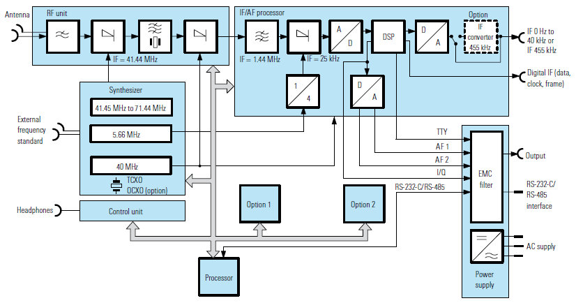
Block diagram of the R&S EK895 receiver
The antenna signal is routed via a lowpass filter, which is provided for rejecting image frequencies and suppressing oscillator reradiation, and applied to the input mixer where it is converted to the first IF of 41.44 MHz by means of an oscillator variable in 1 Hz steps. The crystal filter that follows determines the maximum receiving bandwidth of 10 kHz and rejects the second image frequency. A fixed frequency of 40 MHz is used for conversion to the second IF of 1.44 MHz. The high-performance mixer at the receiver input ensures excellent largesignal behavior. The intercept points are typ +70 dBm (IP2) and +35 dBm (IP3), the crossmodulation transfer is 10% for an interfering signal of +21 dBm.
The second IF is converted to the third IF of 25 kHz using a 5.66/4 MHz fixed frequency. After digitization of the third IF in a 16-bit A/D converter, the processor assumes all signal generation and processing tasks (DSP) including the following: Automatic, remote or manual control (AGC, DGC, MGC). Measurement of received levels. Filtering with fixed or quasi-continuously adjustable bandwidths. Demodulation, passband tuning, double notch filter. Noise blanker. Syllabic squelch. Generation of analog IF output from 0 Hz to 40 kHz or digital IF output as serial data and I/Q data stream.
EK895 review
Your opinion on merits, defects, experiences, with this radio set is welcome. Write your review, after a technical evaluation by our staff if found suitable will be published on this page. We thank you for your precious contribution.
