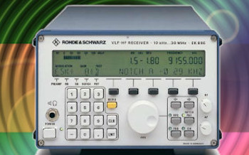
High performance, digital compact radiomonitoring receiver from 9 kHz to 7,5 GHz. Fast panorama scan with up to 1.8 GHz/s across the entire frequency range. Spectrum and demodulation with bandwidths from 150 Hz to 500 kHz. Ideated in Germany.
Reference market : professional
EM100 specifications
| General |
| Frequency coverage | |
|---|---|
| 0.0090 ~ 3500.0000 MHz [1] 0.0090 ~ 7500.0000 MHz [2] |
|
| Mode | |
| CW / LSB / USB / ISB / AM / FM / WFM | |
| Tuning step | |
| 1 Hz min |
| Receiver |
| Selectivity | |
|---|---|
| CW | 0.15~9.0 KHz (-3dB) |
| SSB | 0.15~9.0 KHz (-3dB) |
| ISB | 0.15~15.0 KHz (-3dB) |
| AM / FM | 0.15~500 KHz (-3dB) |
| RF attenuator | |
| Yes (20~3500 MHz) | |
| Features |
| Memory | |
|---|---|
| 1024 locations | |
| Antenna | |
| N 50Ω | |
| Audio output | |
| Jack 3.5 mm headphone | |
| I/Q output | |
| 0.5 MHz bandwidth | |
| Connections | |
| LAN (remote control, I/Q) BNC (21.4 MHz IF output) |
| Mechanical and environmental data |
| Dimensions | |
|---|---|
| 19'' Rack, W ½, 1 HU | |
| Weight | |
| 2.5Kg |
- EM100 base unit.
- With EM100-FE option.
The R&S EM100 digital compact receiver has an excellent feature set for monitoring transmissions, detecting interference, locating miniature transmitters or even functioning as a handoff receiver. In addition, it is extremely compact and consumes very little power. The EM100 is the optimum solution for systems with tight budgets, combining cost efficiency with technical capabilities that yield the desired results. When combined with analysis software (such as R&S CA100), it provides users with a compact receiving and analysis system covering a wide frequency range from 9 kHz to 7.5 GHz. Thanks to its compact size and low weight, the EM100 is ideal for use in vehicles, aircraft (as a payload) and unmanned aerial vehicles (UAV).
EM100 features and key facts :
Fast panorama scan with up to 1.8 GHz/s across the entire frequency range from 9 kHz to 7.5 GHz.
10 MHz IF spectrum and demodulation with bandwidths from 150 Hz to 500 kHz.
Automatic bearing information of emissions with direction finding algorithms (20 MHz to 6 GHz).
Spectrum and spectrogram (waterfall) display via the R&S EM100 control software.
Synchronization of receiver frequency and time using the R&S ESMD-IGT internal GPS module.
High-accuracy timestamps in I/Q baseband data stream for use in TDOA systems.
LAN interface for remote control and data output.
Low power consumption for long-term operation from an autonomous power source.
Classification and analysis of signals up to 500 kHz bandwidth (analog and digital modulation) using the R&S CA100 software.
The Rohde & Schwarz EM100 supports DF (direction finder) functionality when upgraded with the EM100-DF upgrade kit. Using the patented Rohde & Schwarz single-channel correlative interferometer DF method, above 173 MHz, it provides DF accuracy and immunity to reflections comparable to that of direction finders with two or more receive paths. In the frequency range below 173 MHz, the Watson-Watt direction finding method is used. This method offers high DF accuracy even for small DF antennas. In combination with the upgrade kit, the R&S EM100 becomes an accurate, compact and cost effective DF solution.
The receiver is combined with R&S ADD107 and ADD207 compact DF antennas to provide users with a wide direction finding frequency range from 20 MHz to 6 GHz. Both the ADD107 / ADD207 compact antennas come with an integrated GPS system and an electronic compass that can be used to display DF results on a map. When used with the R&S ADD17XZ3 vehicle adapter with magnetic mount or the R&S ADD17XZ6 wooden tripod, the solution allows quick and easy setup of DF stations and mobile direction finders.
Operating principle; Starting from the antenna socket, the frequency in the signal path is limited to 8 GHz for the hardware and 7.5 GHz for the software. Signal processing then takes place in three paths for three different frequency ranges. Signals from 9 kHz to 30 MHz are routed via a preamplifier directly to the A/D converter. Signals from 20 MHz to 3.5 GHz are routed to the IF section through the preselection and a preamplifier, or through an attenuator in the case of high signal levels. Both the preselection and the attenuator effectively protect the IF section against overloading. This is particularly important in this frequency range where the maximum signal sum levels occur. Signals from 3.5 GHz to 8 GHz are routed to the IF section through a preamplifier.
The three-stage IF section processes the signals from 20 MHz to 8 GHz for the subsequent A/D converter. To provide optimum instrument performance, only signals up to 7.5 GHz are processed in the subsequent stages. The uncontrolled 21.4 MHz IF can also be tapped ahead of the A/D converter via a BNC socket for further external processing.
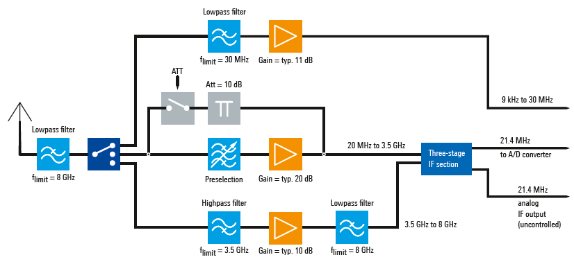
EM100 Rohde & Schwarz, block diagram of frontend
Digital signal processing; After A/D conversion of the signal, the signal path is split. In the first path, the IF spectrum is calculated using a digital downconverter (DDC), a digital bandpass filter and the FFT block. The bandwidth of the bandpass filter can be selected between 1 kHz and 10 MHz. Before the IF spectrum is output via the LAN interface, results are postprocessed using the average, min-hold or max-hold function as selected by the user. In the second path, which also includes a DDC and a bandpass filter, the signal is processed for level measurement or demodulation. To process the different signals with optimum signal-to-noise ratio, the receiver contains IF filters with demodulation bandwidths from 150 Hz to 500 kHz, which can be selected independently of the IF bandwidth.
Prior to the level measurement, the absolute value of the level is determined and weighted using the average, max / peak / RMS or sample function, as selected by the user. The measured level is then output via the LAN interface. To demodulate analog signals, the complex baseband data passes through the baseband filter, then undergoes automatic gain control (AGC) or manual gain control (MGC), and is finally demodulated in the AM, FM, USB, LSB, ISB, pulse or CW demodulation stages. After the AGC/MGC stage, the complex baseband data (I/Q data) resulting from the digitized signals is directly output for further processing.
The selectivity values are available in 15 settings from a minimum of 150 Hz to a maximum of 500 kHz. The selection range is linked to the active mode as shown in the following table:
| Mode / Selectivity | |
|---|---|
| CW, LSB, USB | 150 / 300 / 600 Hz 1.5 / 2.4 / 6 / 9 KHz |
| ISB | 150 / 300 / 600 Hz 1.5 / 2.4 / 6 / 9 / 15 KHz |
| AM, FM, pulse, I/Q | 150 / 300 / 600 Hz 1.5 / 2.4 / 6 / 9 / 15 / 30 / 50 / 120 / 150 / 250 / 300 / 500 KHz |
EM100 review
Your opinion on merits, defects, experiences, with this radio set is welcome. Write your review, after a technical evaluation by our staff if found suitable will be published on this page. We thank you for your precious contribution.
